CHIPnGo Dev #13 - Putting It All Together
After ten painful days of waiting for my PCB to be manufactured and shipped, I finally had it in my hands, ready to be mangled by my terrible soldering skills. I had learned the basics of soldering a couple months prior at my job, and had just purchased my own soldering setup, so it was time to put it to use.
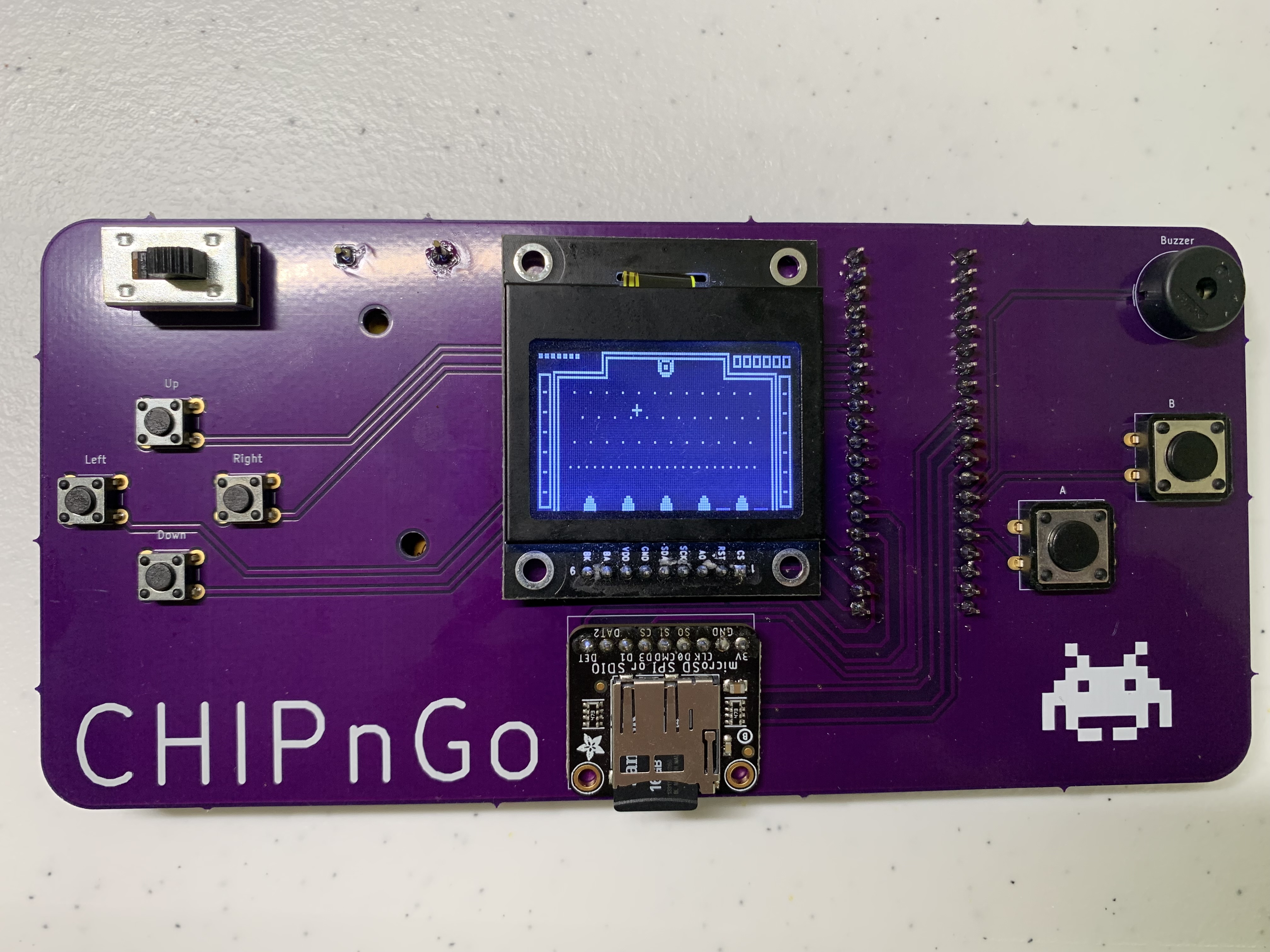
![]() A bit more purple than I was expecting.
A bit more purple than I was expecting.
Despite being mostly easy through-hole soldering, I still managed to run into some issues. First off, my vice was unfortunately too small to properly secure the board while I worked on it, so I had to just set it on the table and deal with it sliding around. Combined with my not-so-steady hands, I was already off to a bad start.
The first annoyance I ran into was that the power switch pins would not fit completely into the holes, so it was left floating a bit above the board rather than flush as I would have liked. I’m not sure if this was by design, or if the manufacturer’s footprint was incorrect, but either way I know now not to 100% trust footprints I didn’t create myself.
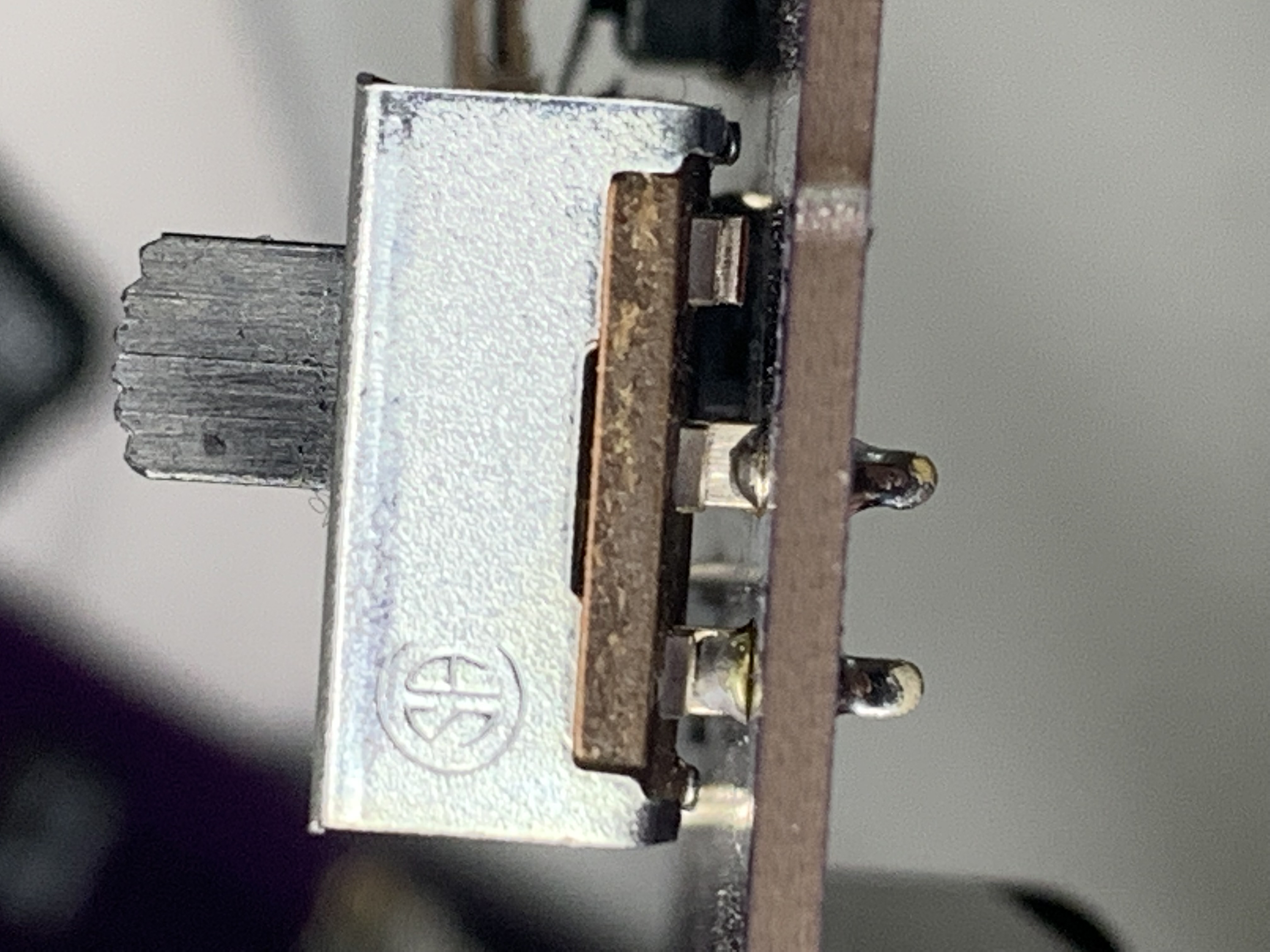 Not ideal.
The next was entirely my fault. I messed up soldering the first pin of the display badly enough that I removed the display so I could start over. Unfortunately, for whatever reason, my solder sucker just was not doing its job of removing the blob of solder left in the hole, so I had to spend the next hour trying to finagle the display back through the hole while awkwardly trying to heat the solder back up. This left a nasty scorch mark on the board and I’m lucky there wasn’t anything too sensitive there.
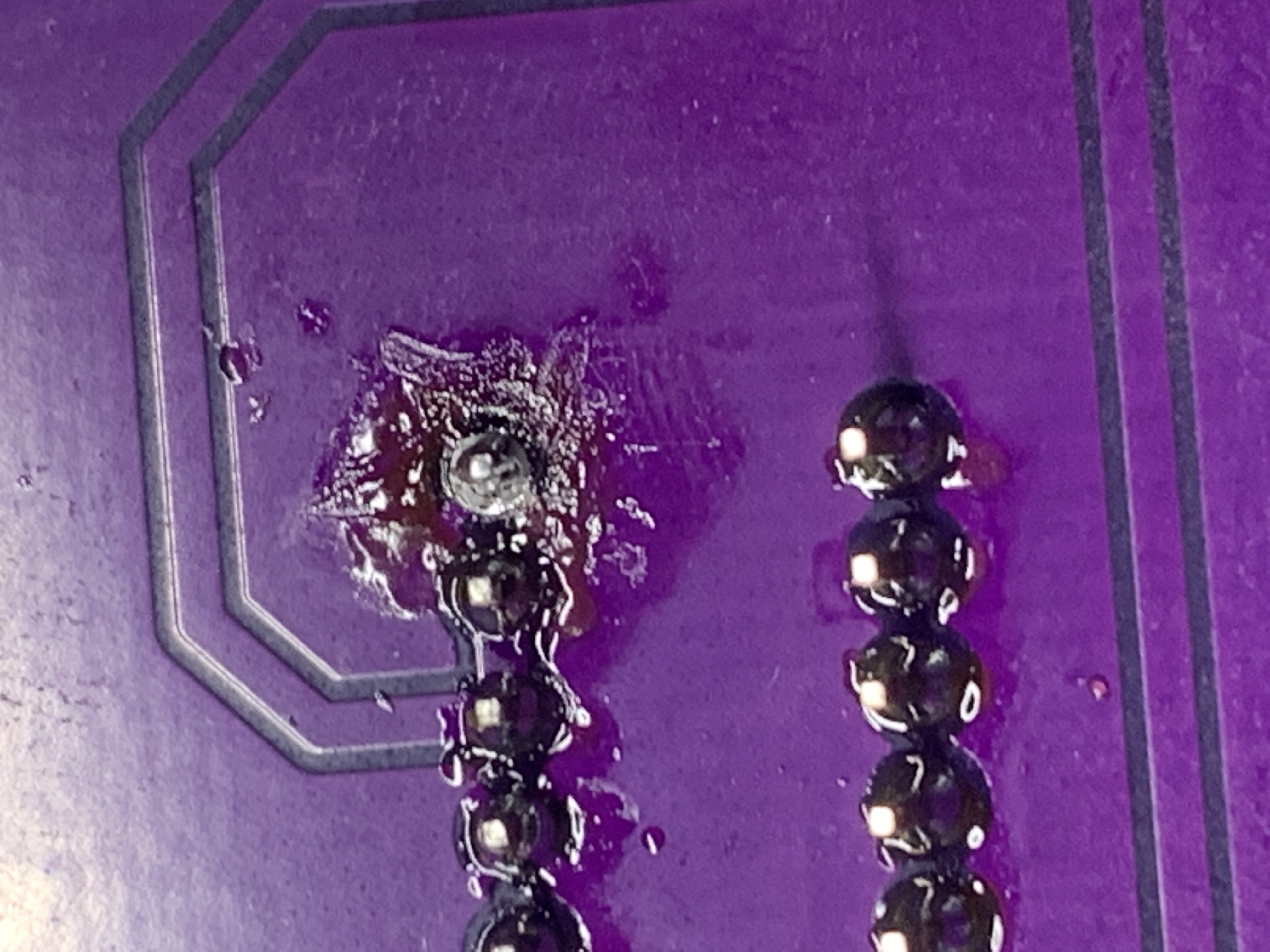 Whoops.
Despite all that work, I could just not figure out a way to get that pin fully through, so I was left with a slightly crooked display. I probably should invest in better tools and training for the future.
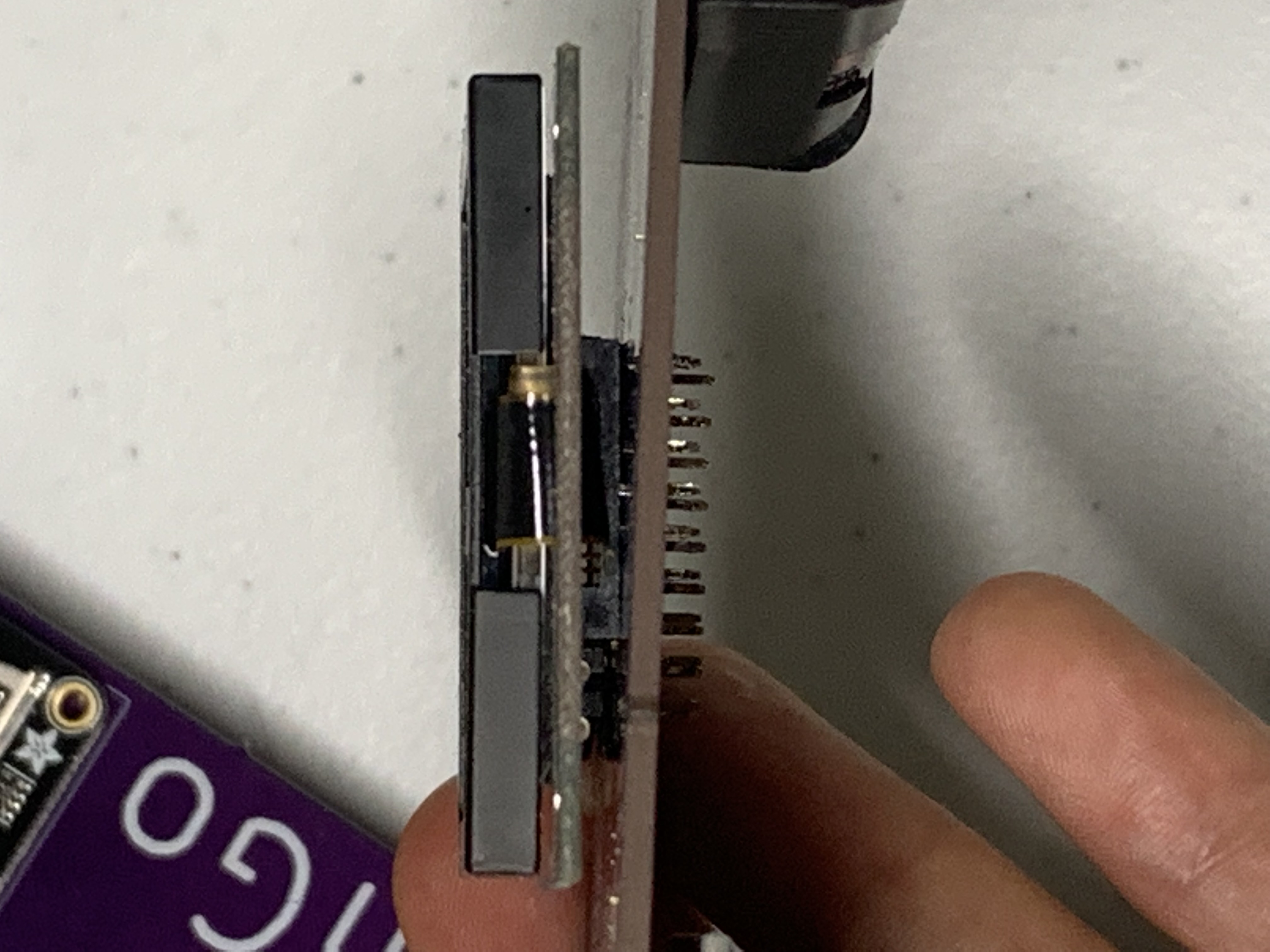 Hardly noticeable, right?
My final screwup was not taking care to ensure the SD reader remained level while I soldered it in. This resulted in the SD reader sitting at a 30 degree angle to the board. Dammit.
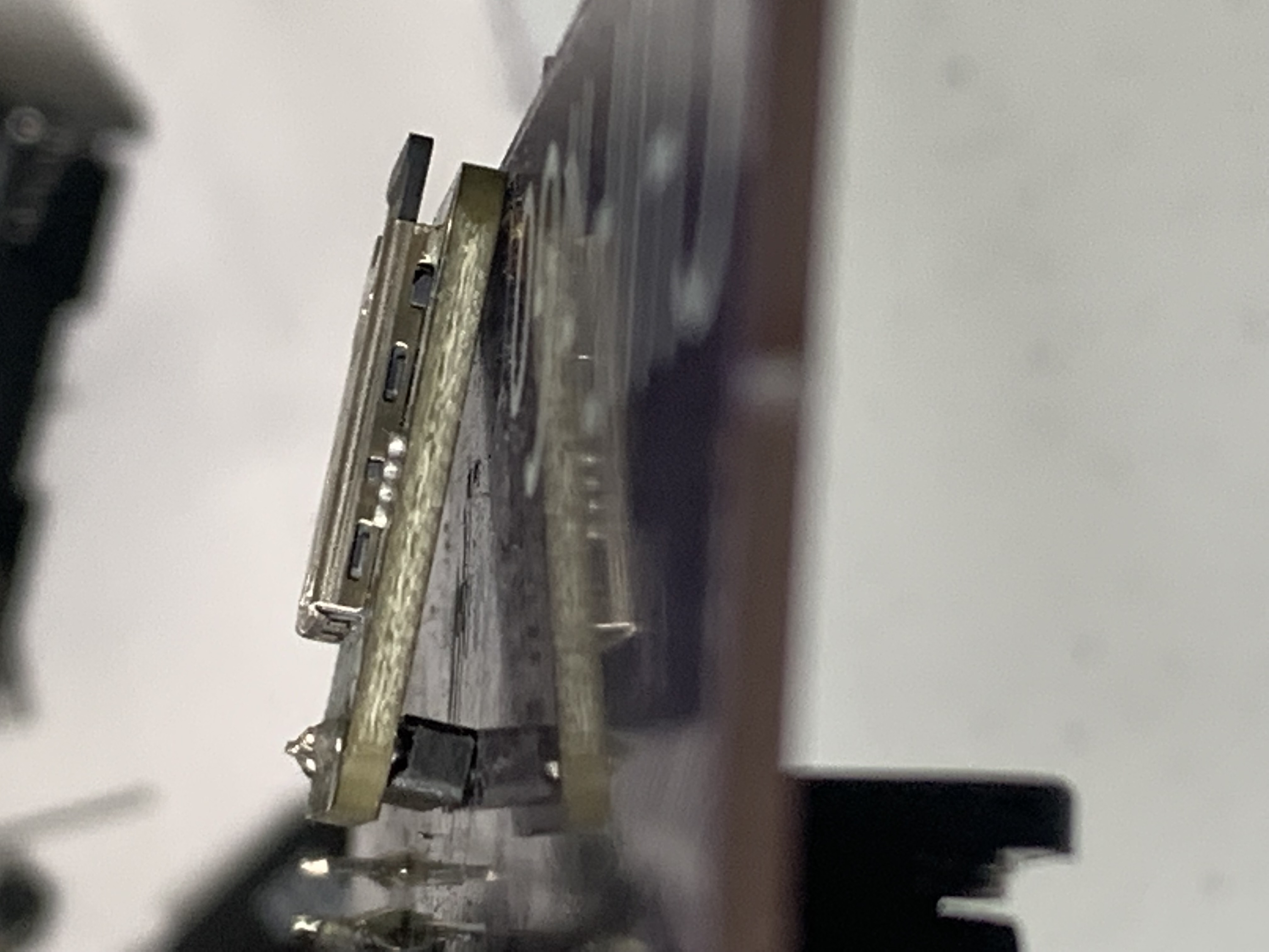 At least it has more stability...
Though with the soldering now done (well, according to certain definitions of the word “done”), it was time for the moment of truth. It was time to see if I was out 90 bucks, or if my hard-work finally paid off. I plopped in a couple batteries and flicked the switch on.
And what do you know, it actually worked! The display fired right up and the buzzer immediately began doing its startup jingle. Soon after, the game selection menu appeared which means I knew it was reading from the SD properly. After playing a couple games for a few minutes, I verified that the buttons were working as expected as well.
Not going to lie, it felt pretty good to get to this point. After several months of sweat and tears, I finally had something that resembled a game console that I designed. The PCB did, however, introduce a strange bug that was not present on the breadboard (where the MCU would seemingly hang after the splash screen but before the game selection menu every now and then) which I oddly enough narrowed down to the GPIO initialization procedure, but it happens rarely enough to not be that big of a deal right now.
All in all, I’m quite pleased with how things turned out. In the final post of this series, I will go a bit into some of the things I’d do differently and my plans for future projects.
 CHIPnGo
| << Prev | Next >> |