CHIPnGo Build Guide
This is a quick guide meant for those who are interested in assembling their own CHIPnGo console, either on a breadboard or with the PCB. Some technical background knowledge is assumed (such as how to install software/use git, how to work with simple electrical components, and basic soldering skills) but if anything remains unclear feel free to email me.
DISCLAIMER: I do not recommend attempting a build unless you feel comfortable potentially making slightly-expensive mistakes. Please do not blame me if you fry or otherwise damage a component. You’ve been warned!
Having said that, if you are not comfortable with building the console yourself and just want one for fun, let me know and if I have the time I may be able to put one together for you just for the cost of the components.
Components
I recommend purchasing the exact components specified, but of course if you know what you are doing feel free to purchase alternatives!
-
Microcontroller: STM32F103C8T6 Dev Board aka “BluePill”. These can usually be found on eBay for a few dollars, however keep in mind the majority of BluePills you find online will be clones. But that is okay, clones are for the most part no different than legitimate BluePills and CHIPnGo was originally made with a clone. Most should come with male header pins but just double-check.
-
Programmer: ST-Link V2 Programmer. There are a couple of ways to program the BluePill, but I recommend using a cheap knock-off ST-Link programmer like the one linked (can be found even cheaper on eBay). Keep in mind that, while it’s technically possible to program the BluePill over serial, I could not get this working on a clone BluePill.
-
Display: ERM12864DNS-8 1.5” 128x64 Monochrome Display. If you purchase from the linked website like I did, just prepare to wait 2-3 weeks for it to arrive from overseas. Should come with male header pins already soldered in.
-
SD Reader: Adafruit MicroSD Card Breakout. Also should come with male header pins.
-
Micro-SD Card: Any micro-SD card over 2GB should do. I say over 2GB because, although you don’t need that much storage, the firmware is written to only work with SDHC cards (which the vast majority of ones over 2GB sold today are).
-
Buzzer: PS1240 Piezo Buzzer. I believe any piezo buzzer that operates in the 3V range should work, however I have only ever tested with the PS1240 specifically.
-
Directional Buttons: 6mm x 6mm Tactile Buttons x 4. Any 6mm x 6mm button should work fine.
-
Action Buttons: 12mm x 12mm Tactile Buttons x 2. Any 12mm x 12mm button should work fine.
The following components depend on if you’re doing a breadboard build or a PCB build.
Breadboard
- Breadboard: Any large, 830 tie-point breadboard will do. Something like this.
- Jumper Wires: You’ll want a general assortment of male-to-male jumper wires of various lengths like this. You can really use any wire as long as you’re able to plug both ends into a breadboard somehow.
- AAA Battery Holder: Presumably if you’re going with the breadboard build you’re not as concerned with portability, so batteries might not be necessary (you can just power directly from USB). But if you are, consider purchasing a 2xAAA battery holder (which connects the batteries in series) with jumper wire connections.
- Breadboard-Compatible Power Switch: This also is not entirely necessary, as if you are just powering over USB turning the console off is as simple as unplugging. If you are going with batteries you can also just disconnect the jumper wires. However if you want, you can still find a power switch that plugs into the breadboard, just make sure it is rated for roughly 50mA DC.
PCB
- Power Switch: GF-123-0054 SPST Switch.
- 2xAAA Battery Holder: 2468 Battery Holder.
And of course, the PCB itself. I will go into detail on how to order the board in the PCB section of this guide.
Uploading Firmware
CHIPnGo was built using VS Code with PlatformIO (an extension that makes building/programming for multiple platforms simple) so this part of the guide assumes you’ll be using that as well. If not, it is assumed you know what you’re doing and will likely need to provide your own linker and startup scripts.
Anyway, as I mentioned, the first step is to install VS Code and then install the PlatformIO extension.
Next, clone the CHIPnGo GitHub repo to whichever folder you’d like, and open the folder in VS Code. If PlatformIO was installed correctly, it should be immediately reocgnized as a PlatformIO project due to the platformio.ini file.
If you are NOT using a BluePill clone (which unfortunately most of the ones you find on the Internet are) remove this line from the platform.ini file:
upload_flags = -c set CPUTAPID 0x2ba01477 ; Remove this line if NOT using a BluePill clone!
Otherwise, just leave it there. Unfortunately there is no easy way to tell if you have a clone, but if you try to program the BluePill with that line in the ini file and it fails, then fortunately you may have a legitimate BluePill!
Next, after ensuring that you do NOT have any other power source connected to the BluePill, connect your ST-Link to the correct SWD pins on the BluePill, and the USB end into your computer. It can be slightly confusing as to which pins on the ST-Link connect to which pins on the BluePill, so if you need some clarification look up some videos on programming a BluePill with ST-Link such as this.
Once conncted, click the “Build” button (the checkmark icon in the bottom of VS Code) to ensure the firmware builds correctly, and then the “Upload” button (the arrow icon next to the “Build” button) to actually upload the firmware. If it gives you any errors, ensure everything is connected properly. Also, for whatever reason, sometimes you just need to hit Upload multiple times before it finally decides to work.
If it told you the upload was successful, you should be ready to go!
Adding Games to SD Card
To make adding games to the SD Card simple, I wrote a tool called Cartridge8. If you have not already cloned the GitHub repository, do that now so that you have the tool downloaded.
You should also download and install Python 3 if you have not already. Once you have done that, install Catridge8 with the following command:
pip install -r requirements.txt
Next you’ll need to insert a micro-SD card that you wish to use for games into your computer. WARNING Cartridge8 will overwrite any data on the SD card, so ensure you are using one that does not have any important data on it and that you wish to dedicate to CHIPnGo.
With the SD card inserted, you’ll need to find the direct path to your raw SD card. On my Linux machine, that is /dev/sda. I’m not entirely sure what it might be on Windows so you’ll have to do some digging around if you’re using a Windows machine.
Once you have the path of the SD card, start Cartridge8 like so:
python cartridge8.py <path-to-SD-card>
Where <path-to-SD-card> is replaced with your SD card path (which in my case, is /dev/sda).
You may need to run the command with sudo or admin privilges if you receive a permissions error.
If it started correctly, you should see a 5x5 grid of tiles where you can add or modify a game.
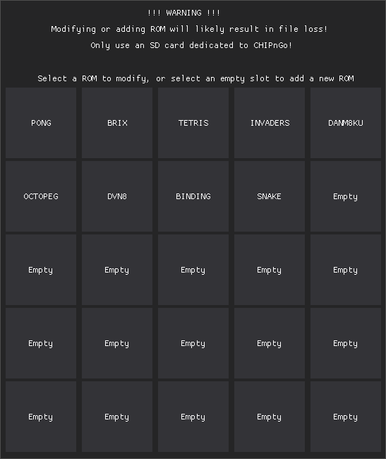
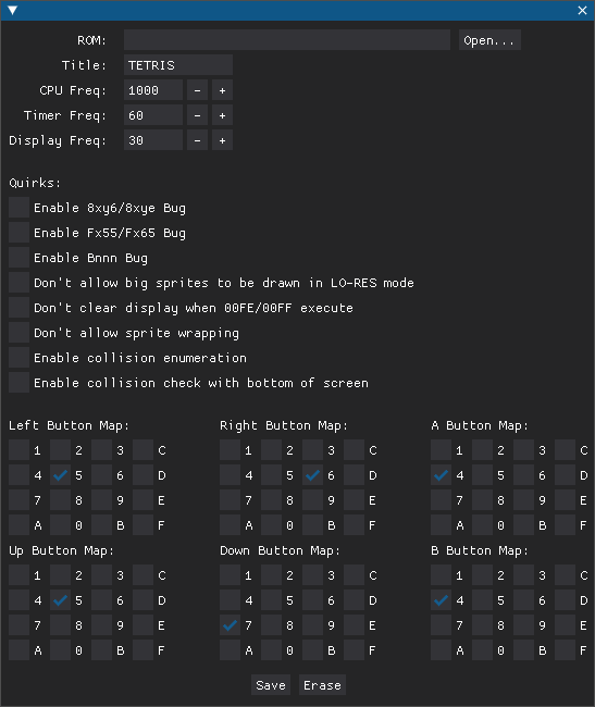
Click any one of these tiles and you will be presented with a game configuration menu. From here, select the ROM file you wish to add, configure it how you like, and click Save. Once you’ve done that, the game should now be on the SD card ready for use by CHIPnGo!
Initial Soldering
Unfortunately, the BluePill and the SD reader breakout do not come with the male header pins pre-soldered, so you’ll likely need to do this yourself, even if doing a breadboard build. You may be able to find these components with the pins already soldered, but I was not able to. So before you begin either build, you’ll need to solder the pins to the breakout boards.
Schematic
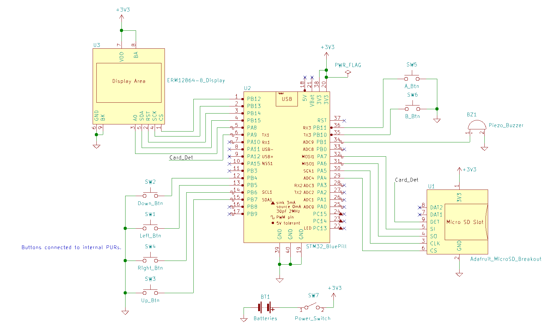
This is the schematic you should be referencing when you make your build (more-so for the breadboard version where you need to actually wire things yourself). Keep in mind that the pin positions on the schematic symbols do not necessarily reflect where they are on the actual breakout-boards (they were rearranged to make the schematic easier to read).
However, the pin labels DO reflect the labels on the breakout boards so as long as you wire things according to the pin labels you should be set. You can also ignore the PWR_FLAG, as that is just used by the schematic software to denote that this pin is in fact receiving power.
Also, a quick note about the buzzer and buttons. The buzzer I used (and linked here) doesn’t care about polarity so you can plug it in whichever direction you like. Some do, however, care about polarity so if you are using a different buzzer make sure to keep that in mind. And most buttons you find today have four pins, despite only really needing two. This is mostly for extra stability, but just know that the pins directly across eachother are connected and the pins next to eachother on either side are not.
Breadboard Build
The placement of components on the breadboard is largely up to you, depending on if you’re just using it to test firmware or if you are trying to make it somewhat ergonomic. Once you have the components placed, it’s as simple as running jumper wires between pins according to the schematic. If you are using a battery pack, you may want to consider mounting the batteries to the back of the breadboard with some sort of adhesive.
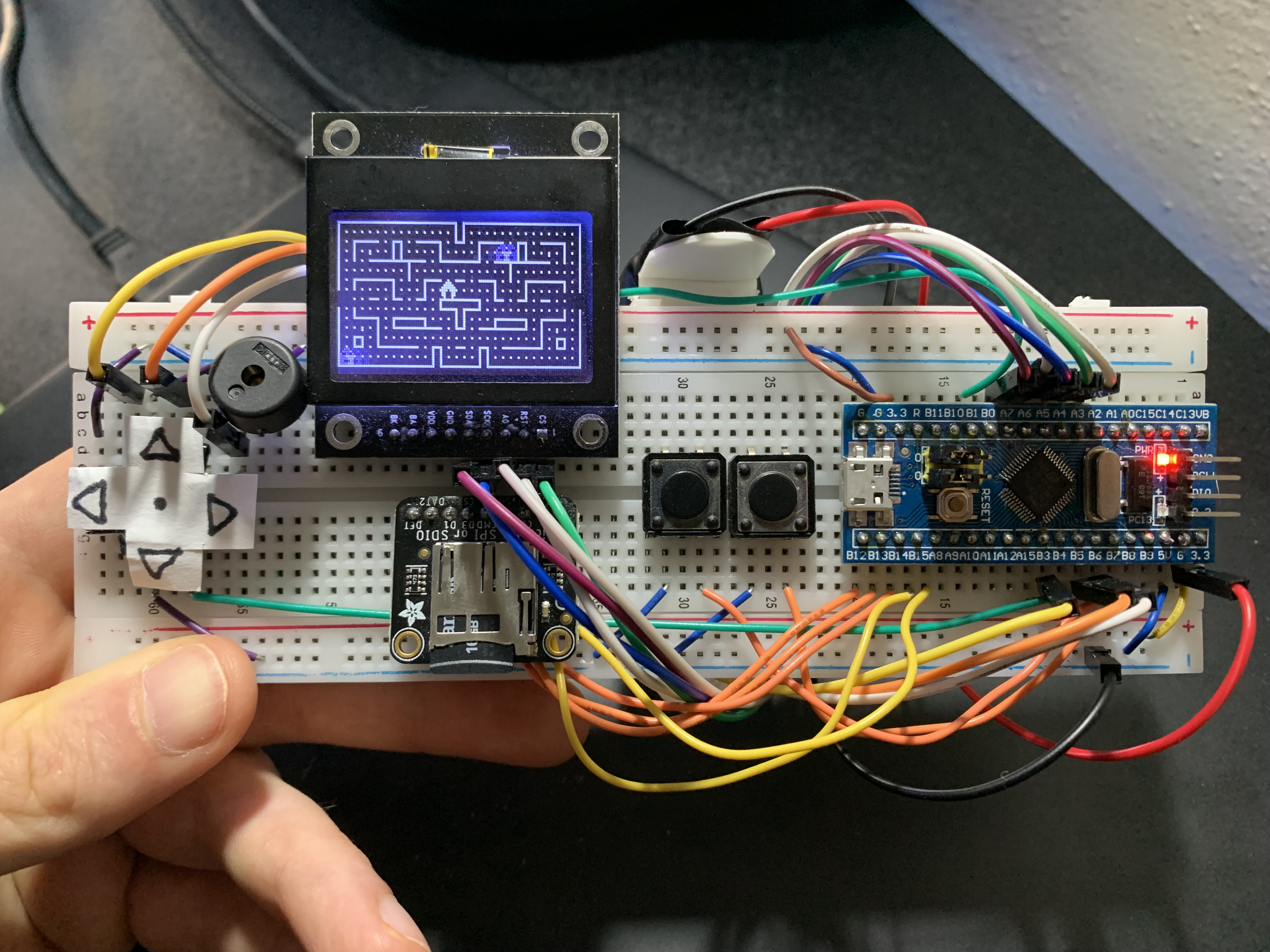
Below you can see the final design I went with for the breadboard prototype. Notice I have the BluePill with the SWD pins out to the right for easy programming, as well as my batteries mounted to the back. The console is then turned on or off by moving the power jumper wire between the power rail (or the 3V pin on the MCU) or an unoccupied spot on the breadboard. I also just used the various lengths/colors of jumper wires I already had lying around, so you could get it to look nicer if you wanted to take the time.
PCB Build
Once you have the components, you’ll need to purchase the PCB as well. Unfortunately, this can be the most expensive part of the project, depending on who you order from. I ordered from OSH Park, who only print a minimum of three at a time, which cost me roughly $100 total. You can likely find a cheaper manufacturer, but keep in mind typically different manufacturers have different board colors (OSH Park is famous for its purple boards) so that’s something to consider if color is important to you.
Anyway, once you have a manufacturer selected, you have to supply them the board files. I designed the PCB in KiCad, and if you order from OSH Park, you can just provide them the CHIPnGo .kicad_pcb file directly. Other manufacturers may only support Gerber files, in which case you’ll need to generate the Gerber files according to the specification of the manufacturer. Feel free to make any modifications to the PCB design before ordering if you know what you are doing.
Also note that the design is quite simple, so does not really push the boundaries of the design rules of any manufacturer that I’m aware of, so you shouldn’t have to worry about this. But, if you want to stay on the safe-side, I recommend ordering from OSH Park since that’s what I went with thus I know it works.
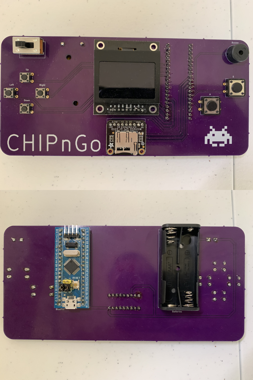
Hopefully by this point you were able to place an order for the PCB with no issues and finally have it in your hands after a couple of weeks. It should look something like this if it was manufactured correctly:
![]()
If you have all the components as well, it’s time to begin soldering. I can’t really offer any tips since I’m still quite the beginner at soldering myself, but just take your time. The silkscreen should make it obvious where components go, but the only real gotchya may be orienting the BluePill correctly. Ensure that it’s oriented such that the SWD pins are pointed toward the top of the board.
A few things to note: Unfortunately the power switch will not sit flush with the board, as the pins will not fit fully-through the holes. This was a goof-up on my part, but luckily it does not affect the functionality. Also, I did not make use of the mounting holes on the display and SD reader so don’t worry about those. Mounting holes are available for the battery holder, though I’m not sure exactly if they are functional because I ended up not using them. Feel free to ignore these if you want. Lastly, I recommend clipping off the leads of the battery holder and buzzer after they have been soldered so you don’t get poked.
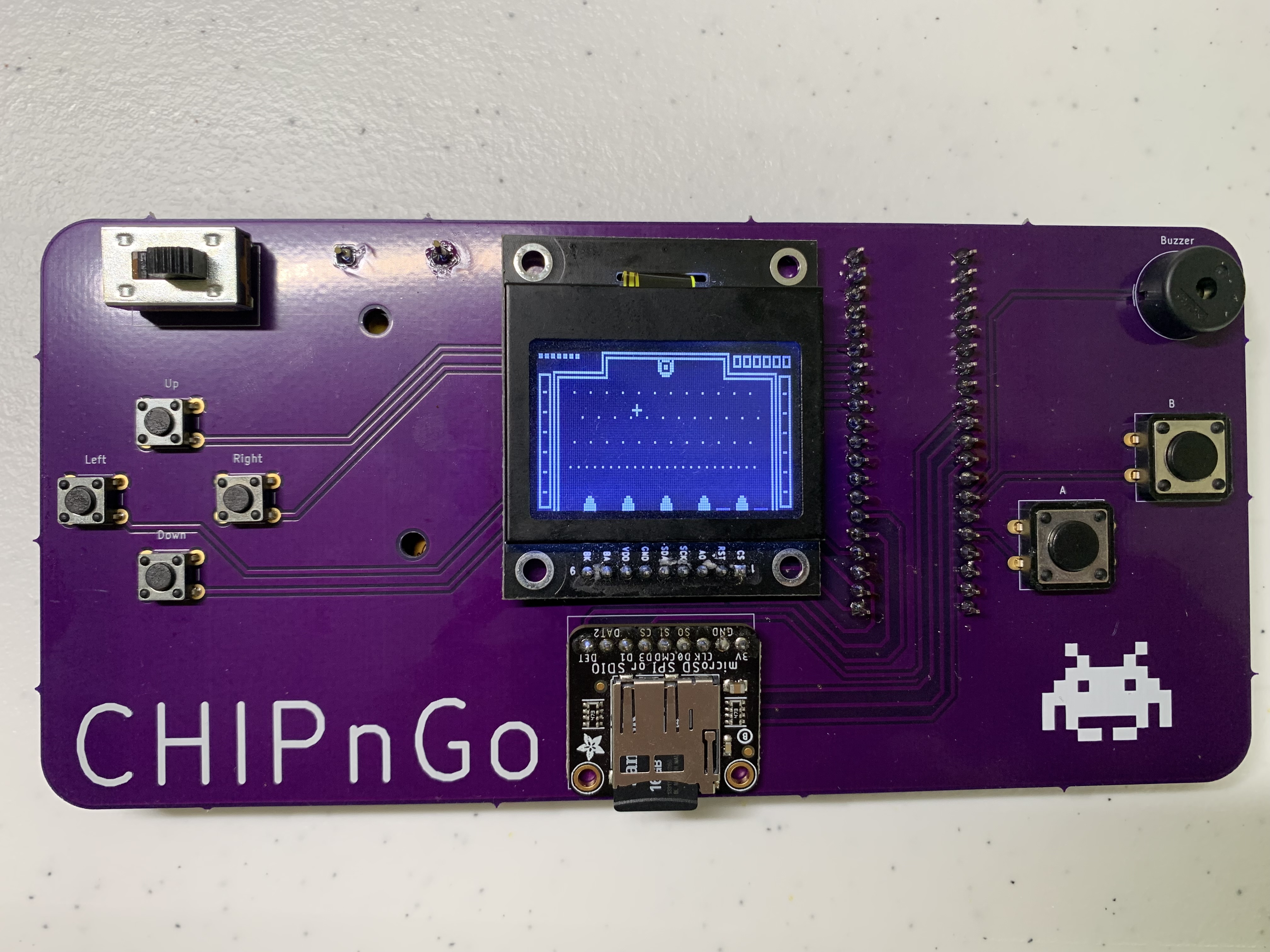
When all is said and done, it should look something like this. Might be a good idea to use this image as a reference for component placement/orientation before soldering as well in case there is any confusion:
Assuming you have already uploaded the firmware and added a few games to the SD card, all that is left is to pop in a couple AAA batteries and the SD card and power it on! Note that there is no reverse polarity protection so if you plug the batteries in backwards you might potentially damage the board, so ensure they are plugged in correctly!
If all went well, you should be presented with the game selection menu and can begin playing games! If not, double check your soldering and make sure you have good connections on every pin. Hopefully you also had the orientation of every component correct as well because otherwise you’re in for a bit of a headache trying to fix that.
Conclusion
If your build was successful, I hope you enjoy playing around with it. Again, feel free to email me if something went wrong and I’ll try my best to help you out.
Although the PCB was not designed with it in mind, you could also consider trying to build a cool case to house the PCB, making it a bit more resillient and aesthetically pleasing. If you manage to come up with something cool, please let me know!
You can also continue to tweak the firmware from here if you desire, and add more games to the SD card. Just remember not to have the power switch on at the same time if you are providing power from USB while uploading firmware, otherwise things could get harry.